Craftsmen, technologists and milling operators of machining shops, whose machine parks have gear hobbing machines, regularly encounter problems in the manufacture of helical cylindrical gear wheels with the question of the most accurate selection of differential gears.
Without going into details of the operation of the kinematic diagram of a gear hobbing machine and technological process cutting teeth with a hob cutter, then this task consists of assembling a two-stage cylindrical gear reducer with a given gear ratio ( u) from the existing set of replacement wheels. This gearbox is the differential guitar. The kit (attached to the machine) usually includes 29 gears (sometimes more than 50) with the same module and bore diameter, but with a different number of teeth. A set may contain two or three gears with the same number of teeth.
The guitar differential circuit is shown below in the figure.

Tuning a guitar differential begins by determining the design gear ratio ( u) according to the formula:
u =p *sin (β )/(m *k )
p– parameter of a specific machine model (a number with four to five decimal places).
Parameter value ( p) individually for each model, is given in the equipment passport and depends on the kinematic drive diagram of a particular gear hobbing machine.
β – angle of inclination of the teeth of the wheel being cut.
m– normal module of the cut wheel.
k– the number of passes of the hob cutter selected for the job.
After this, you need to select from the set the following four gears with the numbers of teeth Z 1, Z 2, Z 3 And Z 4, so that when installed in the differential gear, they form a gearbox with a gear ratio ( u') as close as possible to the calculated value ( u ).
(Z 1 /Z 2 )*(Z 3 /Z 4 )=u’ ≈u
How to do it?
Selecting the numbers of gear teeth to ensure maximum accuracy can be done in four ways (at least that are known to me).
Let's briefly consider all the options using an example gear wheel with module m =6 and tooth angle β =8°00’00’’. Machine parameter p =7.95775. Hob cutter - single pass k =1.
To eliminate errors during multiple calculations, we compose a simple program in Excel, consisting of one formula to calculate the gear ratio.

Guitar gear ratio ( u) read
in cell D8: =D3*SIN (D6/180*PI())/D5/D4 =0,184584124
The relative selection error should not exceed 0.01%!
δ =|(u -u’ )/u |*100<0,01%
For high-precision transmissions this value can be much less. In any case, you should always strive for maximum accuracy in calculations.
1. “Manual” selection of differential guitar wheels.
Gear ratio value ( u) are represented by approximations in the form of ordinary fractions.
u =0.184584124≈5/27≈12/65≈79/428≈ 91/493 ≈6813/36910
This can be done using a program for representing multivalued constants by approximations in the form of fractions with specified precisions or in Excel by selection.
We choose a fraction that is suitable for accuracy and decompose its numerator and denominator into products of prime numbers. Prime numbers in mathematics are those that are divisible without a remainder only by 1 and themselves.
u’ =91/493=0.184584178
91/493=(7*13)/(17*29)
We multiply the numerator and denominator of the expression by 2 and 5. We get the result.
((5*7)*(2*13))/((5*17)*(2*29))=(35*26)/(85*58)
Z 1 =26 Z 2 =85 Z 3 =35 Z 4 =58
We calculate the relative error of the selected option.
δ =|(u -u’ )/u |*100=|(0.184584124-0.184584178)/0.184584124| *100=0.000029%<0.01%
2. Tuning the guitar according to the reference tables.
Using the tables of the reference book M.I. Petrik and V.A. Shishkov “Tables for selecting gears” can quickly solve the problem under consideration. The methodology of work is described in detail and clearly at the very beginning of the book.
Standard set V.A. Shishkova contains 29 gears with the number of teeth: 23; 25; thirty; 33; 37; 40; 41; 43; 45; 47; 50; 53; 55; 58; 60; 61; 62; 65; 67; 70; 73; 79; 83; 85; 89; 92; 95; 98; 100.
Let's use this set to solve our problem.
Result of selection from tables:
Z 1 =23 Z 2 =98 Z 3 =70 Z 4 =89
u’ =(23*70)/(98*89)=0.184590690
<0,01%
3. Differential guitar on-line.
Go to the website at: sbestanko.ru/gitara.aspx and, if your machine model is in the list of source data, then set the parameters of the wheel to be cut and the hob cutter and wait for the calculation result. Sometimes it takes a long time, sometimes it doesn’t find solutions.
For our example, the service did not provide solutions for precision of 5 and 6 decimal places. But for accuracy, 4 decimal places gave 136 options!!! Like - poke around!
The best results presented by the on-line service:
Z 1 =23 Z 2 =89 Z 3 =50 Z 4 =70
u’ =(23*50)/(89*70)=0.184590690
δ =|(u -u’ )/u |*100=|(0.184584124-0.184590690)/0.184584124| *100=0.003557%<0,01%
4. Setting up the guitar differential in the Duncans Gear calculator program.
Using this free program is apparently the best option out of the four offered for consideration. The program does not require installation and starts working immediately after running the gear.exe file. The Help.txt file contains brief user instructions. You can download the program without any problems on the official website metal.duncanamps.com/software.php.
One of the main advantages of the program is that it allows you to find solutions from a set actually available replaceable gears. The user can change the composition of the kit. After turning off the program, the specified set of replaceable gears is saved in memory and does not require re-entry when starting again!
The screenshot below shows the result of the program working with the example under consideration when using the standard V.A. kit. Shishkova.

The most accurate combinations are located at the top of the final list. The result is identical to the results of tuning a guitar differential using reference tables and using an on-line service.
The next picture shows the result of the program when using a set consisting of the standard V.A. Shishkov and two additional wheels with teeth numbers 26 and 35.

The result repeats the result of “manual” selection!
By “manual” selection, we, rather by accident, found the most accurate solution. But the resulting result includes gears with tooth numbers of 26 and 35, which may not be included with the machine.
If you do not get tied to a specific set of replacement wheels, then by unchecking the checkbox, we get sets of four gears that provide the highest achievable accuracy in the above range of tooth numbers. You can make replacement wheels that are not included with the machine and use them when setting up the differential guitar.

After selecting the gears, you should check the possibility of their placement (assemblability) in the guitar body of the machine. The manuals for the machines contain special nomograms that make this easy to do. As a last resort, the assembleability of the differential guitar can be verified experimentally.
Dear readers, please leave reviews, questions, and comments in the comments at the bottom of the page.
Cutting cylindrical gears on a milling machine using a universal dividing head (UDG)
1. Basic provisions
Table 1. Set of eight disc modular cutters
The profile of each cutter of the set is made according to the smallest number of teeth of the interval (for example, for cutter No. 2 at Z = 14), therefore, the greatest error is obtained when manufacturing wheels with the largest number of teeth of each interval. In addition to the error associated with the inaccuracy of the instrument, there is always an error in the operation of the dividing head.
The copying method is used only in individual and sometimes small-scale production.
2. Setting up the machine
The gear blank is secured to the mandrel with a nut. The mandrel is clamped in a three-jaw chuck, which is screwed onto the spindle of the dividing head. The second end of the mandrel is supported by the tailstock (Fig. 2).
The corresponding modular disk cutter is mounted on the machine spindle mandrel and installed in the center of the workpiece. To do this, raise the table until the center of the workpiece mandrel is flush with the bottom of the cutter. Then the table is moved in the transverse direction until the center of the workpiece mandrel coincides with the top of the cutter tooth. After this, the table is lowered and the workpiece is brought under the cutter (longitudinal feed) so that a sheet of thin paper placed between them is bitten. After this, the workpiece is moved away from the cutter, giving the table a longitudinal feed, and the table is raised to the milling depth, counting along the dial.
Before you start cutting teeth, you need to check the setup and adjustment of the machine. Cutting modes – cutting speed and feed are found in tables for processing a given material.
The cutting depth is equal to the tooth height t = h.
3. Universal dividing heads
Dividing heads are important accessories for cantilever milling machines, especially universal ones, and are used when it is necessary to mill edges, grooves, splines, wheel teeth and tools located at a certain angle relative to each other. They can be used for simple and differential division.
To calculate the required angle of rotation of the spindle 1 of the dividing head (Fig. 4), and therefore the mandrel 7 with the workpiece 6 fixed on it, a dividing disk (dial) 4 is used, which has several rows of holes on both sides, located on concentric circles. The holes on the disk are intended for fixing handle A in certain positions using the locking rod 5.

Rice. 4. Kinematic diagram of the universal dividing head (UDG)
Transmission from the handle to the spindle of the dividing head is carried out via two kinematic chains.
During differential division, stopper 8 is released, securing the dial to the body of the dividing head, the worm pair 2, 3 is turned off, and when the handle with the dial is rotated, transmission to the spindle is carried out via the chain:
Where i cm is the gear ratio of the replaceable gears.
With simple division, the replaceable gears are disabled, the dial is stationary, the locking rod is recessed in the handle, when rotated, movement is transmitted to the spindle through a chain:
The characteristic of the dividing head N is the reciprocal of the gear ratio of the worm pair (usually N = 40).
3.1. Setting the dividing head for simple division
When setting the dividing head for simple division, the replaceable gears are removed and the equation of the kinematic adjustment chain has the following form:
 ,
,
where Z 0 is the number of divisions that need to be performed;
a – the number of holes on the concentric circle of dividing disk 4 corresponding to the calculation;
c – the number of holes to which handle A moves;
Z chk – number of teeth of the worm wheel;
K – number of worm passes.
From the equation it follows:
 ,
,
Where Z chk = 40; K = 1; Z 1 = Z 2, from here:
Attached to the dividing head (UDGD-160) is a dividing disk having seven concentric circles with holes on each side.
Number of dividing disk holes:
On one side - 16, 19, 23, 30, 33, 39 and 49;
On the other side - 17, 21, 29, 31, 37, 41 and 54.
The maximum diameter of the workpiece is 160 mm.
Setting example
Set up the dividing head for processing gear Z 0 =34:
![]() .
.
Therefore, to carry out this division it is necessary to make one full revolution of the handle and on a circle with the number of holes 17, turn the handle at an angle corresponding to 3+1 holes and fix it in this position.
To install the handle with a lock on the required circle of the dividing disk (Fig. 5), you need to loosen the clamping nut, turn the handle so that the lock rod falls into the hole in the circle, and re-fasten the nut.

To count divisions, use a sliding sector, consisting of two rulers 1 and 5, a clamping screw 3 for fastening them at the required angle, and a spring washer that keeps the sector from arbitrary rotation.
After determining the required circle on the dividing disk and the estimated number of holes to which the latch should be moved, the sector is set so that the number of holes between the rulers is one more than the number obtained by counting (positions 2 and 4), and it is turned immediately after moving the latch . The sector should remain in this position until the next division, and it should be brought to the hole smoothly and carefully so that the latch removed from the fuse enters the hole under the action of a spring.
If the handle is moved beyond the required hole, it is pulled back a quarter or half a turn and brought back to the corresponding hole. For accurate division, the handle with the lock should always be rotated in the same direction.
The number of turns of the handle for simple division is given in the appendix. 1, for differential division - in adj. 2.
3.2. Tooth size control
Having cut the first tooth, you need to measure its thickness with a caliper or caliper and the height of the tooth with a depth gauge.
Tooth thickness S = m a,
Where m is the gear module in mm;
A – correction factor (Table 2).
Table 2. Dependence of the correction factor on the number of teeth
This material is based on lectures from the Department of Materials Technology (MTM)
From the point of view of technology and kinematics, such a process as gear cutting, is one of the most difficult operations performed during the processing of workpieces on metal-cutting machines. Operations by cutting of cogwheels s are classified as very labor-intensive, since during their implementation it is necessary to remove a considerable volume of metal in order to provide the necessary geometric configuration of the finished product, and in such a way that exact compliance of the tooth profiles with the design parameters is ensured.
The procedure for cutting teeth on gears involves the use of technological processes such as milling, planing, grinding, chiselling, broaching, rolling, and some others.
To achieve the required tooth profile configuration when cutting gears two main methods are used: rolling (circling) and copying (dividing).
Copying method for cutting gearsAccording to this common method, when cutting gears Using the copying method, the cavity that is located between the teeth is cut with a specialized cutting tool (broach, disk or finger cutter, cutter, grinding wheel), which has the same profile as the cutting edges themselves. According to the technology, it must coincide with the profile that the cavity of the wheel being processed has.
When using milling machines for gear cutting using the copying method, disc modular cutters are used. Separately, with each single division, a strictly defined wheel tooth is cut.
Most often, with the help of disk cutters it is produced cutting teeth on gears, which are used as spare parts for various machines and mechanisms. This method is effective for the manufacture of piece goods or small batches. It should be noted that it does not allow achieving high precision in the manufacture of finished products.
Teeth cutting using a disk cutter, it is produced as follows: the workpiece is fixed in a dividing head located on the table of the milling machine; it makes a translational movement along the longitudinal feed to the cutter, which rotates while being fixed in the spindle. Thanks to this, a groove is cut in the workpiece corresponding to the configuration of the cavity located between the teeth. At the end of one operation of this process, using the dividing head, the workpiece is rotated and fixed in the next position, and the processing process is repeated again, and so on until all the teeth are cut.
Gear cutting methods
Finger modular cutters are in most cases used to produce gear cutting having a large module, on milling machines. A prerequisite for the successful performance of such work by qualified personnel is the necessary configuration of the cutting tool: the profile of both finger and disk cutters must necessarily coincide with the profile of the cavities located between the teeth of the wheel being processed.
The operating mode of finger milling cutters is quite complex: they experience significant loads, and therefore they often “squeeze”, which negatively affects the accuracy of the processed products. In addition, it is necessary to take into account the fact that the cutting tool has a conical shape, which means that increased cutting conditions cannot be used when processing it.
Rolling method for cutting gearsAt cutting gears using the rolling method, the formation of the shape of a gear tooth occurs by rolling in a gear pair, the component of which is the workpiece itself, and the other is the cutting tool. In practice, it is advisable to use it only in mass production, since it is necessary to produce high-precision tools (special cutters).
Another fairly common production method gear wheels is the use of hob cutters. This cutting tool has a trapezoidal shape in normal cross-section, and from the point of view of geometric configuration, it is a rack tooth with certain front and rear sharpening angles.
Teeth cutting with the help of hob cutters it is carried out in the traditional way: the cutting tool is given a rotational movement, and the workpiece is given a translational movement in combination with a rotational one. As a result of this combination of movements, involute gear tooth profiles are obtained.
For the manufacture of gear wheels so-called dolbyaks are also used. They, along with hobs, are universal tools. If we talk about all the methods used for manufacturing gears, then among them the most productive and accurate is rolling.
for the first selection group of gears i 4 = 1/j 3 ; i 5 =1/1;
for the second selection group of gears i 6 =1/ j 4 ; i 7 =j 2.
After the gear ratios of all gears included in the kinematic diagram have been established, it is necessary to determine the number of teeth of the gear wheels.
LECTURE 5
4.4. Calculation of gear tooth numbers
The number of teeth in group gears can be calculated using the least common multiple method or a tabular method. The least multiple method is most suitable for the case where the gear ratios are ratios of prime numbers.
To reduce the range of gear cutting tools and reduce the cost of the machine, the modules of all gears of the same group should be made identical. In this case, the width of heavily loaded gears is increased or they are made from higher quality materials, while maintaining performance.
When calculating the number of teeth, the most typical case is the calculation of a gear group consisting of spur gears (inclination angle bj== 0) of the same module.
Least common multiple method
Since the center-to-center distance w for all gears of the group is a constant value (Fig. 4.9) and is equal to
then, with the same module of the gear wheels, the relation should be true
where a w is the center-to-center distance of the gear group ;
m - module in mm;
b j - angle of inclination of teeth;
: Sz is the sum of the numbers of teeth of the mating wheels;
z j and z’ j .-number of teeth of the driving and driven wheels.
Gear ratio of a pair of gears
From equations (4.13) and (4.14) it follows
Let ij = -^" = - L, where f j and g j are prime numbers. Then the formulas for calculating the number of teeth will take the form
Since z j and z" j must be expressed as integers, the sum of the numbers of teeth S z must be a multiple of (f j + g j), that is
where K is the least common multiple of all sums (f j + g j) of the calculated group of gears;
E - integer; E = 1; 2; 3; ...
If the number of gear teeth, calculated according to formulas (4.16), is less than the permissible value determined by the condition for cutting the teeth, that is, Z min< 17¸18, то

The E min value is rounded to the nearest higher integer. If, for design reasons, it turns out that the sum of the teeth is unacceptably small, then it is increased an integer number of times to an acceptable value. On the other hand, the sum of teeth S z should be no more than 100-120.
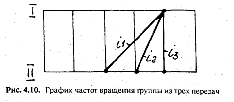
Example. Calculate the number of teeth in the main gear group according to Fig. 4.9 and 4.10. Denominator j = 1.26. From the graph (see Fig. 4.10) we determine the gear ratios of a group consisting of three gears and write them in the table. 4.3.

For the gear ratio i min = 7/11, we determine E min by taking z min =18;
E min =18(7+11)/7*18"3; then the sum of the teeth will be
S z = E" *K = 3 * 18 = 54. Using formulas (4.16), we find

The number of teeth in any drive group is calculated
In a similar way. .
Table method
To facilitate calculations of the number of teeth of group gears, table is given. 4.4 indicating the numbers of teeth of the smaller gear. Empty cells mean that for a given amount S z the gear ratio cannot be maintained within the required limits with a maximum permissible error of ±10 (j-1)%.
When determining the number of teeth according to the table. 4.4 for the calculated group of gears, the sum of the teeth of the mating wheels S z is selected so that the ratio of the numbers of teeth of this sum Z j /Z¢ j provides all the gear ratios of the mating pairs in this group. The sum of the teeth of the mating wheels S z should not be more than 120.
Example. Determine the number of teeth of three pairs of mating gears that should provide gear ratios
If according to the table 4.4 take, for example, Sz=76, then when
I 1 =1/2.82; z 1:z¢ 1 =(76-20):20 and when i 2 =1/2; and i 3 =1/1.41 we have empty cells. Therefore, it is necessary to find a value of S z that satisfies all three gear ratios.


