Federal Agency for Education
State educational institution higher professional education
“MATI” – Russian State Technological University named after K.E. Tsiolkovsky
Department of “Mechanics of Machines and Mechanisms”
PROFILING OF INVOLUTE GEARS
Guidelines for course design on “Theory of Mechanisms and Machines”
Compiled by: Gatsenko A.A. Shuvalova L.S.
Moscow 2006
Andrey Aleksandrovich Gatsenko Lyudmila Sergeevna Shuvalova
PROFILING OF INVOLVENT GEARS
METHODOLOGICAL INSTRUCTIONS
To course design for the course<<Теория механизмов и машин>>
Editor M.A. Sokolova
Signed for printing Volume 1.25 pp. Circulation 150 copies. Order no. from
Rotaprint MATI-RGTU, Bernikovskaya embankment, 14
ACCEPTED DESIGNATIONS AND DIMENSIONS OF VALUES______ 4
1. GENERAL INSTRUCTIONS _____________________________________________ 5
1.1. INITIAL DATA ___________________________________5
1.2. OPERATING PROCEDURE _____________________________________ 5
2. CALCULATION OF GEOMETRICAL PARAMETERS OF CYLINDRICAL
SKY INVOLVENT GEARS OF EXTERNAL MESHING
Research Institute ____________________________________________________________ 6 2.1. CHECKING THE CORRECTNESS OF THE CALCULATION____________________8
3. CONSTRUCTION OF AN INVOLUTE GEARING OF TWO COGS
FOREST_______________________________________________________________9
4. CONSTRUCTION OF MACHINE GEARING________________15
4.1. CONSTRUCTION OF THE INITIAL PRODUCING CIRCUIT
REIKI ______________________________________________________________15
4.2. DETERMINING THE POSITION OF THE INITIAL PRODUCTION RACK RELATIVE TO THE WHEEL TO BE CUTTED_________________15
4.3. DETERMINING THE POSITION OF THE CENTER OF THE CUTTED CO-
FORESTS_________________________________________________________________16
4.4. CONSTRUCTION OF THE MESH LINE PN__________________16
4.5. CONSTRUCTION OF THE LEFT GEAR TOOTH PROFILE______ 16
4.6. CONSTRUCTION OF THE RIGHT GEAR TOOTH PROFILE_____17
4.7. CONSTRUCTION OF A TOOTH TRANSITIONAL CURVE______________17
LITERATURE______________________________________________18
ACCEPTED NOTATIONS AND DIMENSIONS OF VALUES
m – engagement module, mm Z 1 – number of gear teeth Z 2 – number of wheel teeth
Z 1 min – minimum number of gear teeth cut without undercutβ – tooth inclination angle, degrees
P – rack tooth pitch, mm
α W – center distance, mm
r in 1,r in 2 – radii of the main circles of the gear and wheel, mm r w 1,r w 2 – radii of the initial circles of the gear and wheel, mm r 1, r 2 – radii of the pitch circles of the gear and wheel, mm r a 1,r a 2 – radii of the circles of the vertices of the gear and wheel, mm
r f 1 ,r f 2 – radii of the circles of the gear and wheel cavities, mm ρ and – radius of rounding of the tooth stem, mm
h – gear or wheel tooth height, mm H PC – total rack tooth height, mm
S – rack tooth pitch thickness, mm
S 1 , S 2 – thickness of teeth along the arc of the pitch circle of the gear and wheel, mm
S а1,S а2 – thickness of teeth along the arc of the circle of the pinion and wheel vertices, mm
P 1X, P 2X – tooth pitches along the chord of the pitch circle of the gear and wheel, mm
α – profile angle normal to the original contour, deg α t – end profile angle of the original profile, deg
α W1 ,α W2 – gear and wheel engagement angles, degrees
τ 1, τ 2 – pitches of angular teeth of the gear and wheel, degrees X 1 – gear displacement coefficient
X 2 – wheel displacement coefficient
X 1 min – minimum displacement coefficient when cutting a gear C* – normal radial clearance coefficient of the original contour C* t – coefficient of the initial contour radial clearance
y – equalization bias coefficient
h* a – head height coefficient of the original contour
ε α – end overlap coefficient of a spur gear ε β – end overlap coefficient of a helical gear ε γ – total overlap coefficient λ 1 , λ 2 – slip coefficients for gear and wheel υ – specific pressure coefficient.
1. GENERAL INSTRUCTIONS.
On the third sheet of the course project on TMM, the design of an involute spur gear is carried out, containing calculation and graphic parts.
The calculation part includes the determination of geometric parameters gear wheels and some quality transmission indicators.
The graphic part is performed on a sheet of A1 format. This part of the course project contains:
a) machine gear engagement with the rack; b) involute gearing of gears.
1.1. Initial data
1) Number of gear teeth- Z 1 and wheels -Z 2.
2) Module - m, mm.
3) Parameters of the initial contour for a rack and pinion tool according to GOST
13755-81: α =20°;h a * = 1;C* = 0.25;ρ and = 0.38m,
where α is the rack tooth profile angle;
h a * - head height coefficient; C * - radial clearance coefficient;
ρ and - radius of curvature, mm
1.2. Operating procedure
1) Calculate geometric parameters.
2) Construct a machine gear and tool gear
3) Construct an involute gear engagement and gear wheel.
4) Show active areas of the tooth profile on the side surfaces of the contacting teeth.
5) Based graphic construction determine the end overlap coefficientε α and compare it with the calculated value of ε α ras.:
εα | ε α− ε αras | 100% . |
|
εα |
|||
2. CALCULATION OF GEOMETRICAL PARAMETERS OF CYLINDRICAL INVOLVENT GEAR TRANSMISSIONS OF EXTERNAL
GEARS.
Select the value of the displacement coefficients X 1 and X 2 taking into account the recommendations of GOST 16532-70 for power gears. These recommendations are shown in Table 1.
The following condition must be met:
Offset factor | Application area |
||
10 ≤ Z 1 ≤ 30 |
|||
Z 1 > 30 |
|||
Determine the engagement angle α W
invα W = invα + | 2(X 1+ X 2) | tgα. | |
Z 1+ Z 2 | |||
The values of the involute angle of the profile inv α are given in Table. 2.
Table 2. The value of the involute angle of the profile inv α.
inva | |||||||
inva | |||||||
inva | |||||||
inva | |||||||
Note to table 2. Intermediate values of the involute profile angle inv α are determined by linear interpolation.
Determine the perceived displacement coefficient
Z 1+ Z 2 | cosα | |||
− 1. |
||||
cosα W | ||||
Determine the equalization bias coefficient
y = (X1 + X2 ) − y.
Determine the radii of the main circles
r in 1,2= r 1, 2cos α
r W1 | |||||||||
u+1 |
|||||||||
r W2 | |||||||||
where u = | |||||||||
Gear ratio. |
|||||||||
Determine the radii of the wheel top circles
a 1, 2 | + (h * +X | − y)m |
|||
Determine the radii of the circles of the wheel depressions
r f 1, 2= r 1, 2− (h a * + C * − X 1, 2) m
Find the height of the wheel teeth
h = m(2 ha * + C* − y)
Determine the thickness of the teeth on the vertex circle
tgα | ||||||||||
r in 1.2 | ||||||||||
S a 1.2 | 2 r a 1.2 | Invα − invar ccos | ||||||||
a 1.2 | ||||||||||
Determine the transmission end overlap coefficient
2 π1 | |||||||||||||||||
α a 1.2 | Arccos | r in 1.2 | |||||||||||||||
r a 1.2 | |||||||||||||||||
Find the angle between the line of centers and the axis of symmetry of the tooth
h 1.2= r a 1.2sin ϕ 1.2
Find the angle between the symmetry axes of adjacent teeth
Determine the distance between the center line and the intersection point of the axis of symmetry adjacent tooth with a circle of vertices
h 1.2* = r a 1.2sin(γ 1.2− ϕ 1.2) |
2.1. Checking the correctness of the calculation
Determine the center-to-center distance through the radii of the pitch circles and compare it with the value obtained in equation (4)
Check that the teeth are not sharpened. The recommended non-sharpening condition for gear and wheel teeth, respectively:
Sa1.2 ≥ 0.25m

3. CONSTRUCTION OF AN INVOLVENT MESHING OF TWO WHEELS
Having calculated all the main dimensions of gears using the formulas
(1)…(20), begin to depict the elements gearing. The construction is carried out on the left half of the sheet to scale
3.1. Draw a line of gear centers, on which the center distance is plotted on a selected scale a W =O 1 O 2 (Fig. 1).
3.2. Circles are drawn from centers O 1 and O 2: initial circles with radii W1
and r W2 touching the point P in the engagement strip; divisive -r 1 and r 2, fundamental
the tops are r in1 and r in2, the peaks are r a1 and r a2, the bottoms are r f1 and r f2.
To avoid further errors, you should check the distance between the circles of the tops of one wheel and the bottoms of the other,
![]()
measured along the center line, i.e. the amount of radial clearance, which should be equal to C*m.
3.3. Through point P, draw a line of engagement N 1 N 2 tangent to the main circles at points N 1 and N 2 so that it is inclined towards the rotation of the drive gear wheel. Show the engagement angle α W using the engagement line and the perpendicular kO 1 O 2 drawn through the engagement pole P. The straight lines N 1 O 1 and N 2 O 2 are perpendicular to the line of engagement and also form an angle equal to α W with the line of centers O 1 O 2 .
H.4. Construct involute wheels touching at the gearing pole P and limited by the main circles - the beginning of the involute - and the circles of the vertices - the end of the involute tooth profiles (Fig. 2).
The involute of the first wheel, which is described by the point P of the straight line NP when the latter rolls without sliding along the main circle, is constructed in the following order:
a) the segment N 1 P is divided into an arbitrary number of equal parts "a". In this case, the shorter the selected length of the segments, the more accurately it will coincide with the length of the arc. It is recommended to divide the segment N 1 P into three equal parts. Let's denote point N 1 with the number “3”;
You will need
- - a computer with an installed computer-aided design system;
- - drawing tools (patterns, rulers, pencils) for drawing on paper;
- - tracing paper or paper;
- - printer or plotter for printing the drawing (if necessary).
Instructions
Select the material needed to calculate the gear. To do this, you will need the text GOST 16532-70 on calculating the geometry of gears. You can use other reference books, for example, special books for the calculation of such transfers, which will indicate the necessary formulas.
Find out the initial data that you will need to complete the gear drawing. Typically, to construct the initial tooth outline and image of the gear, parameters such as the gear module and the number of teeth are required. The dimensions and shape of the initial contour of the teeth must comply with GOST 13755-81.
Draw a gear drawing, following the rules set out in GOST 2.403-75 and GOST 2.402-68. As a rule, one type with a cut is sufficient. Do not forget that the image of the gear must indicate the diameter of the tops of the teeth, the width of the ring gear, rounding radii or chamfer sizes for the edges of the teeth, and the roughness of the side surfaces of the teeth. If the gear contains additional structural elements (grooves, holes, recesses, etc.) that are not possible in one view, draw an additional view.
Place a table of gear ring gear parameters on the drawing. The table should consist of three parts, which are separated from each other by a solid main line. In the first part, indicate the basic data: module, number of teeth, normal initial contour, displacement coefficient, degree of accuracy and type of mating. Provide an image of the original contour of the tooth with the required dimensions, if the parameters indicated in the table are not enough to determine it. In the second part of the table, enter data to control the relative position of opposite tooth profiles. In the third part of the table, indicate the pitch diameter of the gear and other reference dimensions.
To adjust the split gear on 16-valve VAZ-2110-2112 engines, install camshafts with split gears. Based on the marks of standard gears, approximately set the valve overlaps. Move the pistons of cylinders I and IV to TDC and put on the timing belt. Install dial indicators and their bar (these indicators determine valve movements and TDC positions). Alternately find the closed (zero) positions of the exhaust and intake valves of cylinder IV. After this, using split gears and indicators, set the overlaps of the intake and exhaust valves. Tighten the retaining bolts on the split gears. Reassemble the engine and perform a test drive.
Setting up split gears on 8-valve classic VAZ cars. Having installed the camshaft with a split gear, use the marks of the standard gear to approximately set the valve overlaps. Move the pistons of cylinders I and IV to TDC and put on the timing chain. Install the dial indicators with their feet resting on the rockers.
Alternately setting the closed positions of the valves of cylinder I and the exact position of TDC, set the required valve overlaps along the split gear. Don't forget about the rocker gear ratios and the point on the rocker where the indicator rests. This will make adjustments to the ceilings. If installing an equal-phase camshaft, simply find its zero position (when all valves are open equally), neglecting the values of the rocker multipliers. Lock the split gear, assemble the engine and start it.
A gear is a part of a gearbox mechanism that serves to transmit the power of an electric motor to a working machine. These wheels are most often used with straight and oblique teeth in cylindrical and bevel gears.

Instructions
Gears with straight teeth are used to carry out straight rotational movement drive shaft to driven shaft. If such movement is carried out at any angle, oblique or bevel gears are used, in which the tooth has a variable modulus along its length.
Bevel gears are drawn along the initial large diameter of the circle, so the depressions are not drawn in the main view.
To make a drawing, measure and calculate all elements of the gear wheel in accordance with GOST 9563-60. Determine the outer diameter of the protrusions, teeth De, engagement modulus t, initial circle diameter d, pitch t, tooth height L, tooth head height h", tooth stem height L", inner circle diameter Di, tooth thickness s, cavity width se, working wheel width b, hub length 1X, shaft hole diameter dt, hub outer diameter d2. All letter designations are adopted in accordance with OST VKS 8089.
Typically, tooth profiles are drawn in a simplified manner, using circular arcs. Draw circles of given diameters De, d, Di with a solid main line. Using a thin line, draw an additional circle along which the arcs outlining the tooth profile are located.
Place additional information about the engagement module, the number and angle of inclination of teeth, etc. in the parameter table in accordance with GOST 9250-59, which is located in the upper right corner of the drawing.
Video on the topic
note
Also, in accordance with GOST 2.403-75 ESKD, a profile section of the gear is drawn. Draw the lines indicating the circles and forming the surfaces of the teeth protrusions as a solid main line. The lines indicating the circle of the depressions are dashed lines. Do not shade the teeth that fall into the cut plane.
The popularity of gears is explained by their high efficiency, high load capacity, small dimensions, strength, durability, ease of use and reliability. Disadvantages include high requirements for accuracy of calculation and installation.
When the gear and the toothed wheel meshed with it rotate, an amazing thing happens, imperceptible to the eye. When the side surfaces of the gear tooth and the wheel tooth are in contact, there is almost no slipping! Gear tooth profile rolls...
With a slight slip along the wheel tooth profile!
Why and how is this possible? Because the working surfaces of the teeth are the lateral surfaces of involute cylinders. The end of the wheel (more precisely, part of the tooth) is the base of this cylinder. The intersection of the end plane and the above cylinder is a curve called an involute.
Modern science considers the brilliant Dutch scientist Christiaan Huygens to be the “father of evolutes and involutes”. Huygens discovered (or created) the theory of these curves in 1654.
When you're 17 years old, 1654 seems incredibly far away. But today, when I am much older, I understand that my grandmother, born in 1892, saw and heard in her childhood old people - contemporaries of Pushkin, and even, perhaps, Napoleon - and from the beginning of the 21st century to the first half of the 19th already “at hand”. The eyes of someone close to me, into which I looked many times, saw people who lived in the first half of the 19th century. Incredible! And there, just as many more - the times of Huygens...
Minimizing slip in gearing ensures very high transmission efficiency and significantly reduced wear of tooth profiles because the rolling friction coefficient is at least an order of magnitude lower than the sliding friction coefficient.
All engineers and mathematicians know how to construct a simple involute of a circle. Judging by Internet forums, only a few people know how to construct a tooth profile with an involute and a transition curve.
Who needs this and why?
Firstly, for students of mechanical engineering specialties to perform coursework on the theory of mechanisms and machines.
Secondly, to designers of drives and cutting tools.
Thirdly, to manufacturers of gears on plasma cutting, electroerosive and laser machines.
It is the third group that I hope will find the algorithm presented below particularly useful.
Calculation of coordinates of tooth profile points in Excel.
To perform cumbersome and rather complex calculations, we launch the MS Excel program. You can also perform this calculation in the Calc program from free office packages Apache OpenOffice or LibreOffice.
For helical wheels the profile is constructed for the end section.
Initial data:
We will “cut” the tooth profile with a rack tool – a comb or a hob cutter. We will take the parameters and coefficients of the original circuit according to GOST 13755-81. Look at the drawing of the original rail and understand what it is.
The first four parameters in cells D3-D6 characterize the original contour.
The next five initial data in cells D7-D11 are the “passport” of the gear, providing comprehensive information about it.
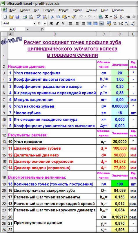
Calculation algorithm:
The results of calculations of the profile angle and all diameters were obtained using the following formulas:
10. α t =arctg(tg(α )/cos (β ))
11. d a = d +2* m *(h a * + x — Δ y )
12. d = m * z /cos(β )
13. d b = d *cos (α t )
14. d f = dA -2* m *(2*h a * +c* —Δ y)
Part of the tooth profile is an involute of the main circle with a diameter d b. Thus, an involute can exist in a gear from the diameter of the main circle to the diameter of the tooth tips!
The second part of the tooth profile is the transition curve from the involute to the diameter of the cavities.
I selected the number of points n each of the curves for its example is equal to 100, considering it sufficient for the required construction accuracy. If you want to change it, you will need to expand or narrow the table “Coordinates of tooth profile points” accordingly, which contains 100 rows ( i max =n).
The results of auxiliary constants are determined by the formulas:
16. D =2*m *((z /(2*cos (β )) — (1-x )) 2 +((1-x )/tg (α t )) 2) 0,5
17. h dy =(d a -d b )/(n -1)
18.h γ =γ 1/(n -1)
19. hda =2*Xuh 1 /(n -1)
20. C=(π/2+2*x *tg (α ))/z +tg (α t ) — α t
21. y 0=1- (ρ f * )*sin (α t ) -x
22. x 0= π /(4*cos (β ))+(ρ f * )*cos (α t )+tg (α t )
The preparation is complete, you can calculate intermediate data and directly the coordinates of the tooth profile points in Excel.
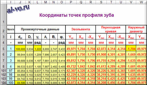
The values in the table are calculated using the formulas:
d y1 =d a
d y (i+1) =d yi -h dy
d y (n) =d b
D i =arccos (d b /d yi ) -tg (arccos (d b /d yi ))+C
γ 1 =π/2-α t
γ (i+1) = γ i -h γ
A i =z /(2*cos(β )) - y 0 — (ρ f * )*cos (γ i )
B i =y 0 *tg(γ i ))+(ρ f * )*sin (γ i)
φ i =(2*cos(β )/z )*(x 0 +y 0 *tg (γ i ))
Yuhi =(d yi /2)*cos (D i )
Xuhi =Yuhi *tg (D i )
YPCi =(A i *cos (φ i )+B i *sin (φ i ))*m
XPCi =(A i *sin (φ i ) -B i *cos (φ i ))*m
X da1 =-Xuh 1
X da (i+1) =X dai +hda
Y dai =((dA /2) 2 — X dai 2) 0.5
After the calculation in Excel is completed, we launch the chart wizard and build scatter plots using the obtained coordinates. How this is done is described in detail.

In the screenshot above, the outer diameter is shown in blue, involutes are shown in dark blue, and transition curves are shown in purple.
The X and Y axes intersect at the center of the wheel - this is the origin point.
Excel built a tooth profile! The problem is solved.
By changing the initial data, you can instantly visually evaluate changes in the tooth profile and see the trimming of the stem or sharpening of the apex when applying a contour offset.
Results.
In order to draw the complete real contour of a gear, you should take the coordinates of the profile points of one tooth and construct a spline using these points in any available CAD program. Then you need to multiply it around the circumference by the number of teeth, complete the diameter of the cavities and get a DXF drawing. Having a drawing, it is easy to write a control program for a CNC machine and produce a part.
Many CAD programs can produce a drawing of the contour of a gear wheel without the described steps, but the contour, unfortunately, in most cases will not be real!
There is an interesting program called Gear Template Generator that generates DXF files of gear outlines (http://woodgears.ca/gear/index.html). However, the initial data for the constructions are somehow unconventional... and the tooth cavities are without radial clearance.
I would like to note that the Excel file offered for download with calculations of the tooth profile in in this case is not a full-fledged program and requires the user to have basic knowledge of MS Excel and an understanding of the geometry of the problem.
In particular, when changing the source data, you will have to manually adjust the axes scales and ensure that the scale along the X axis is equal to the scale along the Y axis (the grid of lines should form squares, not rectangles). When transferring coordinates to a CAD program, the junction point of the involute and the transition curve will have to be adjusted manually, cutting off unnecessary parts of the curves.
The presented algorithm was written (it’s scary to think) in 1992 for a programmable calculator and was intended for drawing control screens for optical grinding machines on a drawing board.
I beg RESPECTING author's work download file AFTER SUBSCRIBE for article announcements.
Dear readers, please write questions, reviews, and comments in the comments at the bottom of the page.
There are several articles on the blog dedicated to gear (and other) gears. The easiest way to find them is by going to the “All Blog Articles” page using the link below:
Articles with similar topics
Reviews
34 comments on “How to build an accurate tooth profile?”
- Evgeny 24 Sep 2015 12:10
- Alexander Vorobyov 24 Sep 2015 14:28
- Alexander Vorobyov 23 Feb 2016 10:31
- 4APK 05 Mar 2016 13:49
- Alexander Vorobyov 05 Mar 2016 16:01
- Yaroslav 11 Apr 2016 13:22
- Alexander Vorobyov 11 Apr 2016 13:38
- Sergey Ermolinsky 14 Jun 2016 20:16
- Evgeny 08 Dec 2016 16:25
- Vladimir 11 Jan 2017 18:52
- Alexander Vorobyov 11 Jan 2017 19:43
- Vitaly 17 Jan 2017 22:01
- Alexander Vorobyov 17 Jan 2017 23:20
- Grayling 09 Feb 2017 23:38
- Alexander Vorobyov 10 Feb 2017 22:50
- Anatoly March 06, 2017 21:18
- Alexander Vorobyov 06 Mar 2017 23:29
- Artem 26 Mar 2017 21:06
- Alexander Vorobyov March 26, 2017 22:19
- Alexander 02 Apr 2017 03:22
- Alexander Vorobyov 02 Apr 2017 11:27
- Alexander 02 Apr 2017 23:09
- Alexander Vorobyov 04 Apr 2017 11:43
- Alexander 08 Apr 2017 23:22
- Alexander Vorobyov 09 Apr 2017 00:06
- Vladimir 03 May 2017 00:30
- Alexander Vorobyov May 03, 2017 08:38
- Igor 07 Jun 2017 19:00
- Alexander Vorobyov 07 Jun 2017 20:32
- Anatoly 10 Oct 2017 20:09
- Alexander Vorobyov 10 Oct 2017 23:07
- Anatoly 17 Oct 2017 19:16
- Alexander Vorobyov 17 Oct 2017 21:40
- Anatoly 18 Oct 2017 12:39

 Echo HSG tubal patency")


